
Product Overview
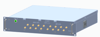
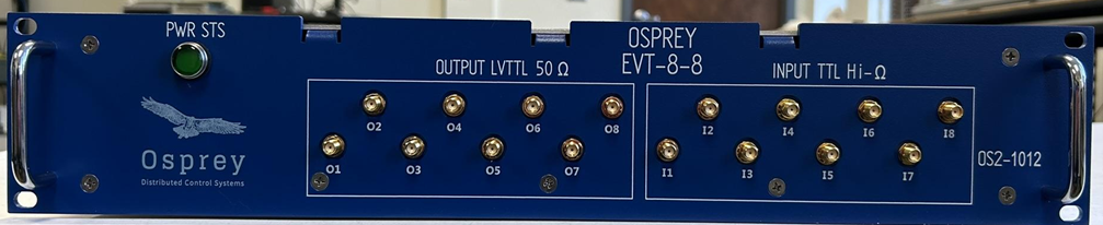
The Osprey EVT-8-8 is a node for distributed timing and trigger systems, configurable as a combined Event Receiver, Machine Protection, and Fast Orbit Feedback endpoint. Each 2U 19-inch rack-mount chassis has 8 TTL inputs, 8 LVTTL digital outputs, and 8 fiber distribution links. As a hardware endpoint, the EVT-8-8 provides synchronized and time-stamped events, triggers, and machine data to local devices. Its transceivers support point-to-point communication for Fast Orbit Feedback and Machine Protection. Full EPICS integration enables real-time system diagnostics and configuration oversight to ensure reliable operation.
Product Overview
The chassis houses an FPGA based on the LBL Marble carrier board and two LVTTL PMOD boards. Digital I/O is accessible via front-panel SMA connectors. Firmware enables synchronization between nodes, and with an EPICS control system to share events and timing data. The chassis provides fiber and Ethernet channels for chassis-to-chassis and server communication.
Key Features
- 8 Inputs / 8 Outputs
- 8 LC duplex fiber connections
- 1 to 6 optical repeater/ fanout
- Channel jitter <20pSec
- Multi-chassis event sync
- Ethernet control and data monitoring
- 2U rack mount form factor
- 12VDC power input
- 2 cooling fans
- Open source hardware, software, and firmware
- EPICS support
Basic Architecture
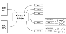
The Marble board is built around a Kintex 160T 7 Series FPGA. This is one of the highest performing FPGAs available from AMD while allowing use of the license-free tool chain. The Marble board is responsible for monitoring, packaging, reporting, and synchronizing all events and triggers from various nodes.
MPS Capability
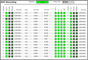
The DAQ-32-250-24 chassis has the EVT-8-8 MPS capability embedded in the FPGA. This screenshot represents the MPS status of 32 chassis with 32 channels each during testing at the NASA SEC facility. This interface aggregates real-time telemetry and MPS status for 1,024 synchronized channels at 50kHz.
Chassis Overview
Front Panel
- Dimensions: 19” x 3.48” (2U Rack Mount)
- Inputs: 8x SMA Digital (High impedance, TTL 5V tolerant)
- Outputs: 8x SMA Digital (50Ω drive capable; 3.3V output)
- Power Status LED; Dual handles
Back Panel
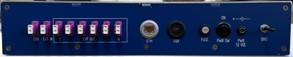
- Dimensions: 16.8” x 3”
- Interface: 8x LC Fiber, Ethernet, MicroUSB
- Power & Protection: DC connector, power switch, 5A fuse, and 8-32 GND screw
- Power Status LED; Dual handles
Internal Architecture
- Carrier: Marble FPGA mounted via 10mm PEM standoffs
- Expansion: 2 LVTTL PMOD connected via J12 and J13 ports
- Thermal Management: Side-mounted fans (inlet/outlet) provide airflow
Tech Specs
EVT - Nominal Performance
- Channel-to-Channel Output Jitter: <20pSec RMS (*channels are located on the same node)
- Digital Inputs: 8x SMA connectors; high input impedance; TTL capable
- Digital Outputs: 8x SMA connectors; 50Ω drive capable; LVTTL
EVT - Absolute Performance
- Ambient Temperature: 0°C - 40°C
- Ambient Humidity: 90% non-condensing max Digital Input abs. Voltage: 6.5V max
- Digital Input abs. Voltage: 6.5V max Digital Output drive current: 90mA max Event Clock Rate: 50MHz - 250MHz
- Event Bitrate: 1Gbps - 5Gbps Number of user-configurable events: 255
Power and I/O
- Power Consumption: 12V DC @ 4.5A per chassis
- Power Connector: 2.1mm barrel plug
- Digital Input/Output Connector: Digital Input/Output Connector:
- Network Connector: RJ45 Gigabit Capable
- Chassis-to-Chassis Connector: 8x Multimode LC fiber
Functional Constraint
Timing fanout and FOFB/MPS modes are mutually exclusive. FOFB/MPS configurations utilize the fanout lines for dedicated communication.
Other Specs
Open source project repos
- github.com/osprey-dcs/ttl-io
- github.com/osprey-dcs/timing-firmware
- github.com/osprey-dcs/timing-ioc
- github.com/BerkeleyLab/Marble
- Request remote board diagnostics such as, temperature, event rates, serial number, etc.
- Updates to firmware can be done remotely through a network connection