
Product Overview
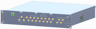
The Osprey EVG-2-16-4 is a timing source in a distributed timing, data and trigger system. Each chassis has 2 clock domain inputs, 16 TTL-compatible digital inputs, 4 LVTTL digital outputs, and 6 timing fanout lines packaged as a 2U 19 inch rack mount chassis.
The EVG-2-16-4 synchronizes receivers by distributing events and data over timing fanouts in a star configuration. This provides time-stamped triggers to connected devices, transmitting time of day, machine mode, and status data. Full EPICS integration provides real-time monitoring of all configuration and internal status to ensure reliable operation.
Product Overview
The chassis houses an FPGA based on the LBL Marble board, an RF clock input FMC board, and an LVTTL PMOD board. Digital I/O is accessible via front-panel SMA connectors. Firmware enables synchronization between nodes, and with an EPICS control system to share events and timing data. Designed for serviceability, the chassis provides fiber and Ethernet channels for chassis-to-chassis and server communication.
Key Features
- 2 clock domain inputs
- 16 Inputs (TTL compatible)
- 4 Outputs (LVTTL)
- 1 to 6 optical repeater/ fanout
- Channel jitter <20pSec
- Multi-chassis event sync
- Ethernet control and data monitoring
- 2U rack mount form factor
- 12V DC power input
- 2 cooling fans
- Open source hardware, software, and firmware
- EPICS support
Basic Architecture
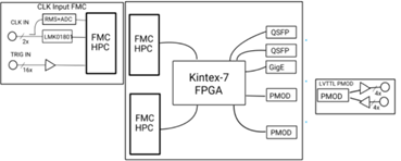
The RF Clock Input FMC board contains 2 independent 50MHz-250MHz clock inputs. These clocks are distributed and sent to the FPGA using Texas Instruments LMK01801 Dual clock distribution chip. The clock input levels are monitored by an Analog Devices ADL5501 for diagnostic purposes. The board has one digital input with a 50Ω input earmarked for a Pulse per Second (PPS) input. An additional 15 TTL-capable digital signalsare provided with a 100kΩ input impedance.
The Marble board is built around a Kintex 160T 7 Series FPGA. This is one of the highest performing FPGAs available from AMD while allowing use of the license-free tool chain. The Marble board is responsible for monitoring, packaging, reporting, and synchronizing all events and triggers from various nodes.
Chassis Overview
Front Panel
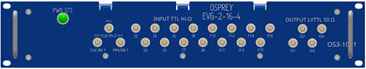
- Dimensions: 19” x 3.48” (2U Rack Mount)
- Inputs: 2x Clock, 15x SMA Digital (High impedance), 1x SMA Digital (50Ω)
- Outputs: 4x SMA Digital (50Ω drive capable; 3.3V output)
- Power Status LED; Dual handles
Back Panel
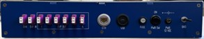
- Dimensions: 16.8” x 3”
- Interface: 8x LC Fiber, Ethernet, MicroUSB
- Power & Protection: DC connector, power switch, 5A fuse, and 8-32 GND screw
Internal Architecture
- Carrier: Marble FPGA mounted via 10mm PEM standoffs
- Expansion: Clock input FMC secured at 4 points; LVTTL PMOD connected via J12 port
- Thermal Management: Side-mounted fans (inlet/outlet) providing direct airflow across the FPGA heatsink
Tech Specs
EVG - Nominal Performance
- Channel-to-Channel Output Jitter: < 20pSec RMS (*channels are located on the same node).
- Clock Input: 50MHz - 250MHz; -5 to +20dBm
- Digital Inputs: 15x SMA connectors; 100kΩ input impedance; TTL capable
- Digital Input (PPS): 1x SMA connector; 50Ω input impedance; TTL capable
- Digital Outputs: 4x SMA connectors; 50Ω drive capable; LVTTL
EVG - Absolute Performance
- Ambient Temperature: 0°C - 40°C
- Ambient Humidity: 90% non-condensing max
- Digital Input abs. Voltage: 6.5V max
- Digital Output drive current: 90mA max
- Clock Input: -5.8 to +25.9dBm
- Event Clock Rate: 50MHz - 250MHz
- Event Bitrate: 1Gbps - 5Gbps
- Number of user-configurable events: 255
Front Panel
- Power Consumption: 12V DC @ 4.5A per chassis
- Power Connector: 2.1mm barrel plug
- Clock Input Connector: SMA
- Digital Input/Output Connector: SMA
- Network Connector: RJ45 Gigabit Capable
- Chassis-to-Chassis Connector: 2x Multimode LC fiber
Other Specs
Open source project repos
- github.com/osprey-dcs/rf-input-fmc
- github.com/osprey-dcs/ttl-io
- github.com/osprey-dcs/timing-firmwaregithub.com/osprey-dcs/timing-ioc
- github.com/BerkeleyLab/Marble
- Request board diagnostics such as, temperature, event rates, serial number, etc.
- Updates to firmware can be done remotely through a network connection